Permanent Way Module Design
Concept
The P-Way module is a physical device designed to drive all of the permanent infrastructure of the layout including:
- Track power and data
- Points (turnouts / switches)
- Signals
- Occupancy (block operation)
A layout may include multiple P-Way modules depending on the number of blocks, points and signals to be driven. For example the Kings Cross layout is expected to require at least seven modules.
The P-Way module is essentially an interface, not a controller. Without a Control Panel to send commands the module will do very little. One possible exception may be local interlocks and frog polarity switching.
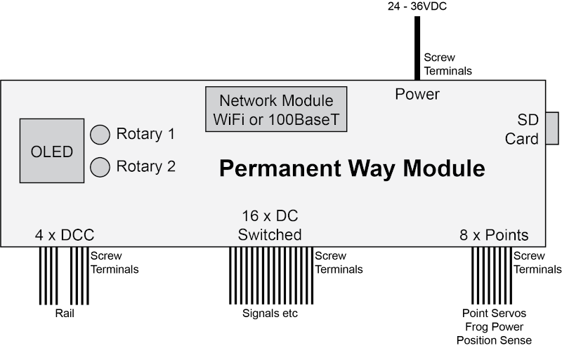
Power
The P-Way module is powered by a DC input between 24V and 36V, low enough to be safely bussed around the layout and high enough to reduce cable losses. Internal power supplies will convert this to the voltages required to power the circuitry, trains, servos, signals and so on. The unit will be protected against excessive current draw and reversed polarity.
Network
Each P-Way module connects to a central network through which it can communicate with the Control Panel and any other connected devices. In designing this we have considered several options including:
- Digitrax LocoNet®
- RS485
- CAN Bus
- 100Base-T Ethernet
- 802.11 WiFi
The first three options have a distinct wiring advantage, in that they can all be daisy-chained. WiFi is even better in that no additional wiring is required, but there is a connectivity risk. 100Base-T requires each node to be cabled back to an Ethernet switch but has a speed advantage over each of the others. Ethernet and WiFi both have futher advantages:
- Open non-proprietary standards.
- Powerful networking stack.
- Guaranteed delivery.
- Comparatively fast data rate.
- Easily connected to the Control Panel with no special gateway.
- Routeable wirelessly, potentially even to trains.
- Potential for direct internet connectivity e.g. for software updates.
For this reason the network interface will be implemented as a submodule, so the final decision can be deferred pending testing. With proper abstraction it would be possible to support multiple networking standards for different applications. Initially Ethernet will be implemented, but WiFi might be a good future option for eliminating a lot of wiring from large layouts.
Rail Power / DCC
The P-Way module provides power for up to four track circuits and can sense current draw individually on each for the purpose of over current protection and occupancy detection. The maximum current available is TBD but circa 1A per circuit.
The module can modulate the rail power with DCC data. Although not required for normal Thinking Trains operation, this broadens the utility of the project and provides the opportunity to run conventional DCC stock and accessories. DCC can serve as a channel for reporting RFID position sensing events to locomotives (see RFID Sensor), and for manual reversion operations.
If multiple P-Way modules are in use one will be assigned as DCC Controller. The other DCC Responder modules will pick up rail data on a DCC input connection either from a rail dropper or direct from another module.
As with most of the P-Way module connections, rail power will be exposed on Phoenix screw-down terminals to accept wire ended terminations.
Accessory Power
The P-Way module provides sixteen channels of general purpose switched DC output for driving low current accessories such as signals, crossing gates and so on. Higher power accessories may be driven via relays. The association of function to output is handled within the Control Panel logic. The total current available for accessories is TBD but circa 1.5A.
Accessory power will be exposed on Phoenix screw-down terminals.
Point Control
Each P-Way module can control up to eight points (or individial elements of compound pointwork such as slips). Although not every signal need be utilised by a given layout, each point interface includes:
- Servo Command (PWM)
- Servo Power (5V)
- Frog Power (switched Rail L/R)
- Normal Position Sense
- Reverse Position Sense
- Ground
This includes everything needed to drive an electrofrog point with a servo motor and optional position sensing switches, without the need for any additional circuitry. Frog power will include DCC if in use. Position sense inputs are considered active when connected to ground, and if both are used enable the Control Panel to indicate both set and in-transit conditions reflecting the true mechanical state at any moment.
AC solenoid point motors may be driven from accessory power outputs via relays and a separate power supply, but the frog and sense signals of the point interface can still be used.
Point connections are exposed on Phoenix screw-down terminals.
User Interface
Although the P-Way module is not intended to provide an interface for operating the layout (this is the role of the Control Panel), it does offer a simple interface for configuration and test purposes.
A small colour OLED screen and two rotary controls with push operation provide sufficient control for setting parameters, activating outputs and running diagnostics.
Memory Card
The P-Way module uses a FAT formatted SD memory card to store settings and any other data that may prove necessary. The card is also used during firmware updating, even if the new firmware image has been provided over the network.
Cards are to be organised intuitively with human readable / editable files wherever appropriate.