Train Driver Module Design
Concept
The Train Driver module is a physical device fitted to each train in a Thinking Trains railway via a standard 6 or 8 pin DCC connector. It is responsible for sensing the position of the train on the track and moving it in response to signals and cab instructions.
This is fundamentally distinct from a conventional DCC train, which is directly controlled by an operator or external software. The Train Driver simulates an actual driver, applying the rules of locomotive operation autonomously. An example block operation might look like this:
- Train is held at a signal at danger
- Railway operator uses Control Panel to set a route
- Signal clears
- Train Driver accelerates to the line limit
- Train passes a caution signal
- Train Driver decelerates
- Train approaches a signal at danger
- Train slows to a halt at signal
To implement the working model the Train Driver must be aware of many of the same sensory inputs as a real world driver. That is, awareness of its position relative to signals and other factors; of the state of signals as they are approached; of line speed limits and hazards; and of signalman instructions sent to the cab.
In response the Train Driver must be able to operate the train by setting the appropriate speed and direction; accelerating and braking smoothly; coming to a halt at a precise position, whether at a signal, terminus or another train; settings running lights and sounding the horn as required.
Locomotive Interface
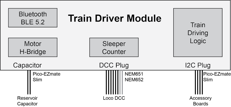
The Train Driver is implemented in the form factor of a DCC decoder, a standard for digital control supported by most model locomotives in the past couple of decades. This allows Thinking Trains to be used with existing models with little modification.
Two versions of the module will be developed - NEM 651 using a 6-pin connection for N-Gauge models, and NEM 652 using an 8-pin connection for OO and HO models. Each connector provides at least:
- Left Rail
- Right Rail
- Motor +ve
- Motor -ve
- Front light
- Rear light
The modules are physically very small, especially the NEM 651 variant in order to fit into existing models.
The smaller module shall be known as Type A and the larger as Type B.
Power
The module is powered from the rail connections. These may be running the DCC protocol so it is necessary to rectify them. Rail voltage is typically 14V and the maxumum sustained current is 0.5A for NEM 651 and 1.5A for NEM 652.
Additional capacitance is included to keep the electronics and motor alive during short interruptions that often occur during train operation. This is provided by an additional board which can be located somewhere with sufficient space within the locomotive.
Motor Control
The train motor is driven using a PWM voltage to set speed, and reversable polarity to set direction. This is accomplished with an H-Bridge driver rated for the size of module.
Accessory Control
The module can directly control the front and rear running lights via the standard NEM interface.
To keep the module size down, some accessories may be provided on separate boards daisy-chained from a wired accessory interface. That interface provides I2C serial data communication, power and ground. Such accessories may include:
- Sleeper Counter
- Sound Generator
- Smoke Generator
Sleeper Counter
To calculate its position along the track, each Train Driver counts sleepers as it moves. For this to be useful the train must know:
- Starting position (datum).
- Direction of travel.
- The route set.
- Offset between sensor and leading or trailing limit of the train.
Counting is achieved by a photo sensor mounted in the bottom of the locomotive facing down to the track, in conjunction with an LED that illuminates the track under the train. Provided there is sufficient contrast between the track bed and sleeper, the counter can detect edges and keep a running tally.
For greater reliability the LED is modulated with a carrier frequency and the receiver filters out any signal outside of that carrier. The wavelength of the light source is typically IR however UV may be utilised to improve contrast when the trackbed and sleepers are similar in colour. The latter requires treatment of either the track bed or sleepers with UV dye. Accuracy can be further improved by using debounce parameters derived from the current speed of travel.
The spacing of sleepers is not necessarily consistent, especially over pointwork and around bends, so sleeper counting is not suitable for deriving arbitrary distances. However when combined with a data map of sleeper counts between points of interest the method can be used to accurately locate signals, buffer stops, platform stops, whistle boards and so on.
Some cumulative error is anticipated with missed or false counts. This is mitigated by regularly resetting to a known datum via the RFID Sensor system.
Wireless Communication
Each Train Driver will maintain a wireless data connection with the Control Panel. This will be the path by which location, signal, control and other data will travel to and from trains. Because of space constraints the most practical choice of wireless standard is Bluetooth 5.x Low Energy (BLE), which is available on tiny modules that are practical to incorporate onto even the Type A module.
Each Train Driver will take the BLE Peripheral role, which means it will advertise its presence and await a connection. The BLE Central role will be taken by gateways connected to the Control Panel network, which will connect to trains when it detects them. The connection will be maintained continuously for minimum message latency. Subject to testing, slower more reliable PHY modes will be chosen such as the BLE 5.0 LE Coded 125kHz PHY.
With careful BLE module selection the possibility exists to implement BLE Mesh networking without changing the hardware.
Rail Communication
Train Driver will be able to decode standard NMRA DCC data. Although this is not a Thinking Trains core capability it does offer some advantages:
- Standard DCC trains may be operated in manual reversion.
- Train Drive may use DCC for its own manual reversion operations.
- Certain data such as RFID sensing may be communicated via DCC as an alternative to BLE.
- Parts of the project become potentially useful to a wider community.
It is not currently intended to implement RailCom, the reverse data channel extension to DCC. As long as BLE proves reliable then RailCom, wihch is something of a hack layered on a hack, is redundant within Thinking Trains.